Mixer
NT series
Outline
Medium and large-sized mixers
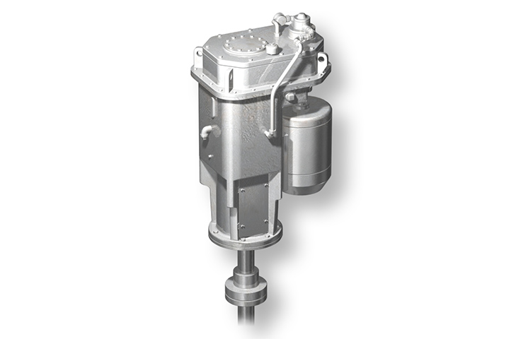
The NT series of mixers uses reducers dedicated for mixers, which made several achievements in the fields of power plants, water treatment, and chemical plants.
They are characterized by a wide variety of sizes that include the largest capacity in Japan and by compatibility that enables mounting in orientations other than top entry.
Features
Reducers dedicated for mixers use our own high-precision gear
The reducers for NT mixers are specially designed for mixers that use our own high-precision gear and achieve long life and low noise.
Selecting double and triple reduction gears allows the selection of amazing reduction gear ratios.
Compatible with all types of seals
The mixing shaft seal is compatible with a wide variety of methods, such as gland, single dry mechanical, and double mechanical seals.
The gas and liquid contact parts can have a variety of different types of linings. Please feel free to contact us because we have a lot of experience in handling special materials.
Diverse mounting positions
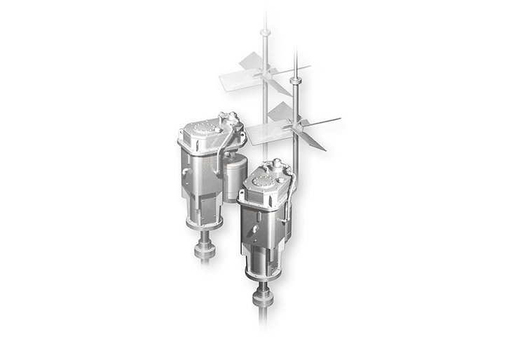
The reducers in this series can be used for a wide variety of applications, such as top entry, which is the typical mounting orientation of the mixer, as well as bottom entry and angled mounting.
Compact design for reducing the required space
Using a reducer with a special motor position enabled a configuration that is smaller than that of other reducers. The products in this series are optimum for conditions with limited ceiling height.
In addition, placing the motor, which is the source of vibration, in a low position achieved vibration reduction.
Applicable to a wide variety of capacities
The standard lineups in this series are applicable to various motor capacities from 1.5 kW to 200 kW. We can offer models compatible with motors with larger capacities at the customer’s request.
Specifications

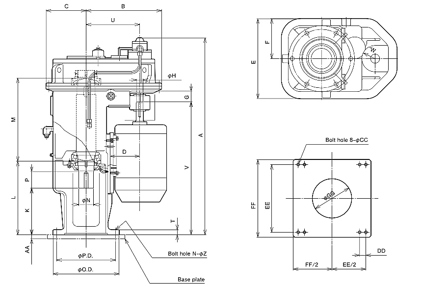
| Series # | A | B | C | D | E | F | Input shaft |
K | L | M | Ouput Shadtt |
T | U | V | W | Size of mounting flange | Approx. weight (kg) |
Approx. oil quantity (litters) |
|||||
|---|---|---|---|---|---|---|---|---|---|---|---|---|---|---|---|---|---|---|---|---|---|---|---|
| G | H | N | P | Nominal diameter |
ΦO.D. | ΦP.D. | N-ΦZ | ||||||||||||||||
| NT108 | 1098 | 394 | 202 | 160 | 404 | 202 | 65 | 30 | 248 | 384 | 480 | 75 | 80 | 20 | 268 | 733 | 60 | JIS10K 200A | 330 | 290 | 12-Φ23 On centerlines |
340 | 12 |
| NT110 | 1192 | 457 | 242 | 180 | 484 | 242 | 65 | 40 | 282 | 442 | 510 | 90 | 100 | 30 | 325 | 807 | 80 | JIS10K 250A | 400 | 355 | 12-Φ25 On centerlines |
520 | 16 |
| NT112 | 1334 | 506 | 269 | 200 | 538 | 269 | 65 | 45 | 314 | 509 | 560 | 100 | 130 | 30 | 365 | 914 | 80 | JIS10K 350A | 490 | 455 | 16-Φ25 Staddle centerlines |
850 | 21 |
| NT116 | 1414 | 588 | 310 | 225 | 620 | 310 | 65 | 45 | 318 | 538 | 580 | 125 | 140 | 35 | 410 | 943 | 100 | JIS10K 400A | 560 | 510 | 16-Φ27 Staddle centerlines |
1100 | 28 |
| NT120 | 1588 | 651 | 340 | 225 | 680 | 340 | 70 | 45 | 348 | 608 | 665 | 140 | 160 | 40 | 465 | 1088 | 100 | JIS10K 450A | 620 | 565 | 20-Φ27 On centerlines |
1600 | 40 |
| NT124 | 1788 | 677 | 350 | 250 | 700 | 350 | 85 | 50 | 352 | 632 | 800 | 150 | 180 | 45 | 490 | 1212 | 100 | JIS10K 550A | 745 | 680 | 20-Φ33 On centerlines |
2200 | 50 |
| NT130 | 2097 | 801 | 420 | 280 | 840 | 420 | 110 | 60 | 387 | 699 | 985 | 180 | 200 | 50 | 576 | 1437 | 115 | JIS10K 650A | 845 | 780 | 24-Φ33 Staddle centerlines |
3850 | 90 |
■Approx. weight does not include weghts of motor and shaft seal.
■As we may change dimensions, please check pur dimensional drawing for confirmation.


